Jul 11th, 2008 by admin | 1 Comment »
Jul 1st, 2008 by Alexandre Quessy | No Comments »
Ver el video. (500 Kb)
LA PERIFERIA
presenta:
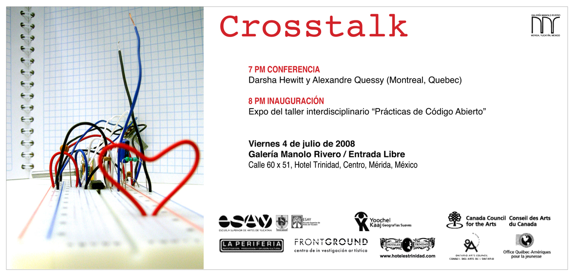
<:><:><:><:><[LiM0tRónICa]><:><:><:><:>
Hechos:
? Hay muchísima gente que come limones en México
? Los limones se pueden usar como baterías.
? Los limones pueden hacer ruido si los obligas a hacerlo.
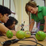
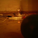
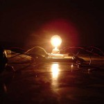
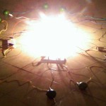
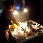
LiMOtrRóniCa es un performance audio/visual experimental e instalación
desarrollada en Junio del 2008 durante una residencia en LA PERIFERIA
(Mérida, México). La pieza consiste en una serie de experimentaciones
electrónicas que utilizan aparatos electronicos hechos a mano,
software de código abierto y limones.
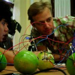
Realizamos alquimia en limones ? los presionamos para hacer sonidos y
los hacemos ?chillar?.
LiMOtRóniCa es una colaboración entre LAN Pa®ty [Alexandre Quessy +
Darsha Hewitt] y los estudiantes en el curso de OPENSOURCE PRACTICES –
COLLABORATIVE APPROACHES AND EXPERIMENTAL ELECTRONICS FOR ARTISTS
llevado acabo en la Escuela Superior de Artes de Yucatán (ESAY).
A los artistas les gustaría agradecer a LA PERIFERIA, ESAY + sus
alumnos de arte, Byrt Wammack y a Ana Rosa Duarte Duarte por su apoyo.
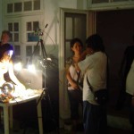
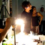
El evento empezará con Ciclanimación, un performance de animación
cuadro por cuadro ejecutado en tiempo real por LAN Pa®ty y los
estudiantes del taller OPENSOURCE PRACTICES – COLLABORATIVE APPROACHES
AND EXPERIMENTAL ELECTRONICS FOR ARTISTS. Ciclanimación utiliza
ToonLoop, un software de contenido generado por los usuarios que fue
desarrollado por Alexandre Quessy.
Jueves 3 de Julio del 2008 // 8 PM
Entrada Libre
Galeria La Periferia
cale 54 #468 x 53 y 55,centro
Mérida, Yucatán, México
52 999 9241923
info@galerialaperiferia.com
www.galerialaperiferia.com
Jul 1st, 2008 by kikedelic | No Comments »

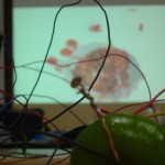
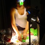
Just letting Darsha enjoy the power of the ReacTIVision Software.
and just to know there’s a little information about the free software.
reacTIVision 1.4
reacTIVision is an open source, cross-platform computer vision framework for the fast and robust tracking of fiducial markers attached onto physical objects, as well as for multi-touch finger tracking. It was mainly designed as a toolkit for the rapid development of table-based tangible user interfaces (TUI) and multi-touch interactive surfaces. This framework has been developed by Martin Kaltenbrunner and Ross Bencina at the Music Technology Group at the Universitat Pompeu Fabra in Barcelona, Spain as part of the the reactable project, a novel electronic music instrument with a table-top multi-touch tangible user interface.
Jun 28th, 2008 by Alexandre Quessy | No Comments »
Here is a piece of code to turn the Arduino into a square waves generator with pitched notes. (musical MIDI-like notes) It is an adaptation of the old MusicalAlgoFun I did post a little while ago. (See this post on my web site for a little video) This time, it plays La Cucaracha.
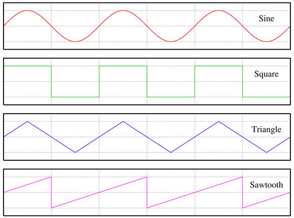
Using a pin as output, if we change it very quickly from HIGH to LOW with a little delay between each change, we can generate a square wave. If you want to generate other audio wave forms, you might want to check the Glade library. You can also get a very nice white noise with a random delayMicroseconds between HIGH and LOW transitions.
I talked enough ! Here is the code :
/*

* La Cucaracha with an Arduino and a PC speaker.

* The calculation of the tones is made following the mathematical

* operation:

*

*       timeUpDown = 1/(2 * toneFrequency) = period / 2

* )c( Copyleft AlexandreQuessy 2006 http://alexandre.quessy.net

* Inspired from D. Cuartielles's http://www.arduino.cc/en/Tutorial/PlayMelody

*/
int ledPin = 13;
int speakerOut = 10;
/* 2 octavas :: semitones. 0 = do, 2 = re, etc. */
/* MIDI notes from 48 to 71. Indices here are from 0 to 23. */
int timeUpDown[] = {3822, 3606, 3404, 3214, 3032, 2862,
2702, 2550, 2406, 2272, 2144, 2024,
1911, 1803, 1702, 1607, 1516, 1431,
1351, 1275, 1203, 1136, 1072, 1012};
/* our song. Each number is a (MIDI note - 48) on a beat. */
//byte song[] = {12,12,12,14, 16,16,14,14, 12,16,14,14, 12,12,12,12,
//14,14,14,14, 9,9,9,9, 14,12,11,9, 7,7,7,7};
byte song[] = {7,7,7,12,12,12,16,16,7,7,7,12,12,12,16,16,16,16,16,16,16,12,12,11,11,9,9,7,7,7,7,7};
// do do do re mi re do mi re re do...
byte beat = 0;
int MAXCOUNT = 32;
float TEMPO_SECONDS = 0.2;
byte statePin = LOW;
byte period = 0;
int i, timeUp;
void setup() {
pinMode(ledPin, OUTPUT);
pinMode(speakerOut, OUTPUT);
}
void loop() {
digitalWrite(speakerOut, LOW);
for (beat = 0; beat < MAXCOUNT; beat++) {
statePin = !statePin;
digitalWrite(ledPin, statePin);
timeUp = timeUpDown[song[beat]];
period = ((1000000 / timeUp) / 2) * TEMPO_SECONDS;
for (i = 0; i < period; i++) {
digitalWrite(speakerOut, HIGH);
delayMicroseconds(timeUp);
digitalWrite(speakerOut, LOW);
delayMicroseconds(timeUp);
}
/* Uncomment this if you want notes to be discrete */
/* delay(50); */
}
digitalWrite(speakerOut, LOW);
delay(1000);
}
Jun 27th, 2008 by Alexandre Quessy | No Comments »

Arduino es una plataforma open-hardware basada en una sencilla placa con entradas y salidas (E/S), analógicas y digitales, y en un entorno de desarrollo que implementa el lenguaje Processing/Wiring.
Su corazón es el chip Atmega8, un chip sencillo y de bajo coste que permite el desarrollo de múltiples diseños.
Al ser open-hardware tanto su diseño como su distribución es libre. Es decir, puede utilizarse libremente para desarrollar cualquier tipo de proyecto sin tener que adquirir ningún tipo de licencia
Arduino puede utilizarse en el desarrollo de objetos interactivos autónomos o puede conectarse a un PC a través del puerto serie utilizando lenguajes como Flash, Processing, MaxMSP, etc … Las posibilidades de realizar desarrollos basados en Arduino tienen como límite la imaginación.
Jun 24th, 2008 by Tonalli | No Comments »
So it looks like it’s done!!! yeaaaaaaaaaaaaaaaayyyyy just need to double check the signal w the chinese sticks, do some sodering, and puts th knobs back in!!
aki el link para que vean el mixeerrrrr
Big thanks to my sensei Darsha san
Jun 23rd, 2008 by darsha | No Comments »
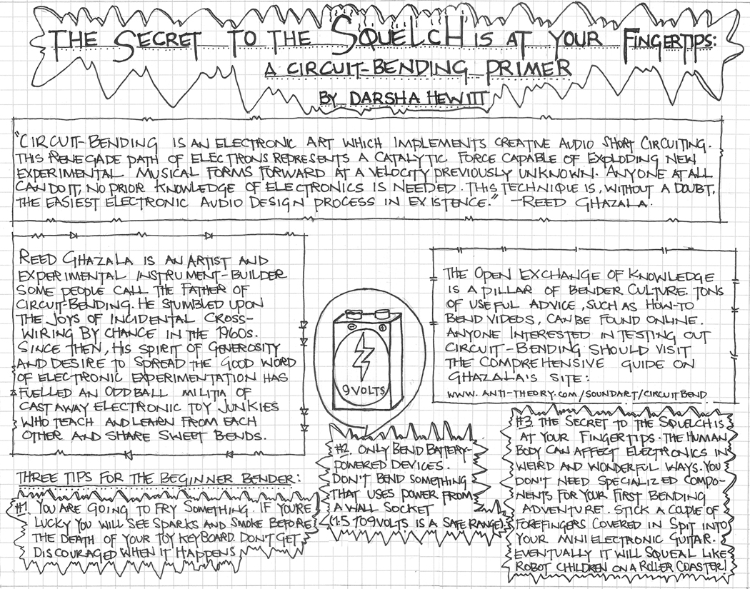
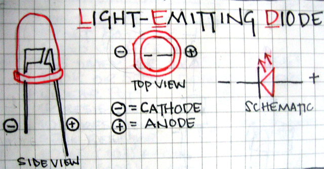
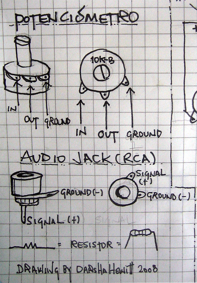
This is a page from your Intro to Circuit Bending guide. Go HERE to download the who guide and learn more about bending
Jun 21st, 2008 by Tonalli | No Comments »
yeah a lot of ideas come out of this….it’s something that Darsha mentioned in class ..(there is a link all the way down if you can’t see this..
so it actually works although it brings down the level quite a bit, kind of like an attenuator pad @ -10db in a mixing board , an interesting thing!!! maybe it would be cool to actually measure the attenuation and see how much is the value @.
we could be selling paper attenuator pads inside a black box and be rich!! hahaha..
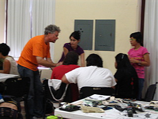
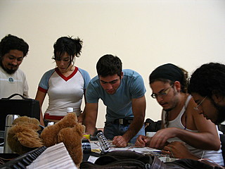
Jun 21st, 2008 by Alexandre Quessy | No Comments »
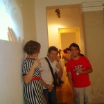
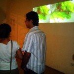
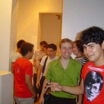
Aquí hay algunas fotografías de este viernes. Semana 1.
Jun 21st, 2008 by Alexandre Quessy | No Comments »
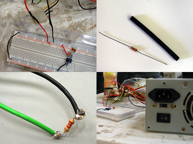
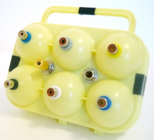
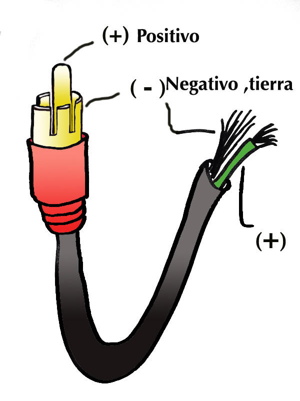
Es muy fácil de usar un fuente de alimentación de computador como fuente de corriente eléctrica de 3.3 voltios, 5 voltios y 12 voltios. Es solo necesario de conectar una resistencia entre el cable verde y cualquiera de los cables negro.
Entonces, puede usar cualquier cable rojo como un fuente de energía de 5 voltios . Las cables naranjas llevan 3,3 voltios. Los cables amarillo llevan 12 voltios.
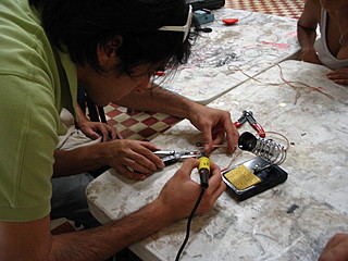
On the image on the bottom left, you can see a lot of solder on both legs of the resistors. You don’t need that much !! It is also better to use heat shrink to prevent from short circuits.
A resistor of 1.0 kOhm works well here. With a smaller value, your power supply would consume a lot of amperes per hour. (then a lot of kW/h) If you use a resistance value that is too big, your power supply will not even start and run.
Here is a link to a page of reference on computer power supplies on WikiPedia.
A quick note about how to choose the right power source : most devices need an accurate voltage level to work, but the amount of amperes it can provide can be of any value – greater or equal of the amperage it needs.
Jun 20th, 2008 by Tonalli | No Comments »
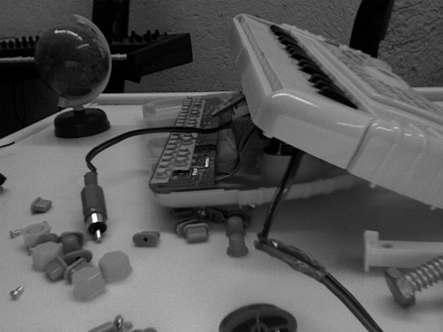
Nop not there yet with the mixer but getting close … here are some pics of the progress!!

despues de pensarlo mucho decidi quedarme otros dias para tomar el taller!!! feliz, asi que os dare lata tios y tias.. joder es que mola mucho el taller.. viva la madre patria.. hahaha.
Jun 20th, 2008 by darsha | No Comments »
see semana 3 for the esquemática y lista de componentes
Jun 20th, 2008 by darsha | 2 Comments »

See Semana 2 for an updated and modified version of the esquemática
Componentes
1 x LM556 (circuito integrado)
1 x 9 volt battery
1 x 9 volt battery clip
1 x audio jack (female rca)
1 x on/off toggle switch
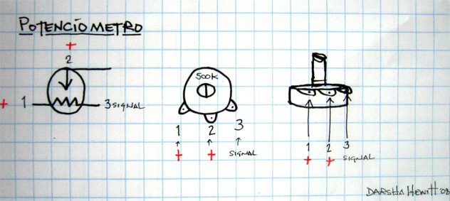
1 x 500k Linear Potentiometer
1 x Alligator clip
1 x 1k resistor (1/4 watt)
1 x 10k resistor (1/4 watt)
1 x 4.7k resistor (1/4 watt)
1 x 10 nf (103) capacitor
1 x 100nf (104) capacitor
1 x 10 uf electrolytic capacitor (polarized) (5 volt to 15 volt wattage rating)
Jun 20th, 2008 by darsha | No Comments »
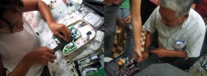
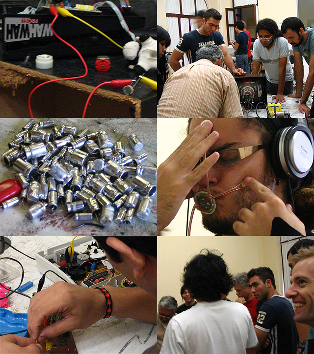
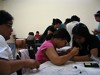
Hola hermanos y hermanas – aquí hay algunas fotos de personas que rasga aparte electrónica


Jun 20th, 2008 by admin | No Comments »
Rutt-etra Video Synthesizer
Woody y Steina Vasulka, 1978
Jun 19th, 2008 by peter mix | No Comments »
pica este link para ver el video del taller….
Jun 19th, 2008 by Alexandre Quessy | No Comments »

Here are a few informations on how to use a 555 Timer to create square waves. It can be used to make sound or to make lights blink, and so on.
Also, check this PDF for a diagram that will be easy to make.
Here is a little explanation on how it works.
…and search on google for «555 timer».
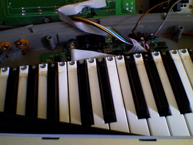
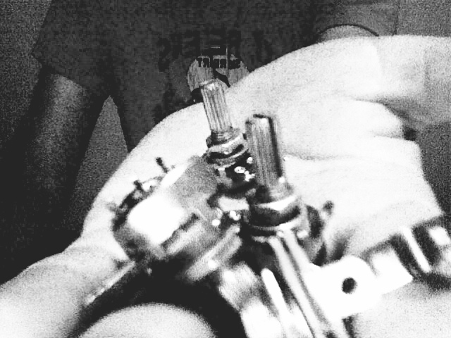
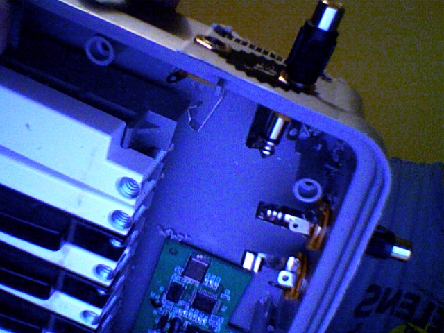
Jun 19th, 2008 by Tonalli | 2 Comments »
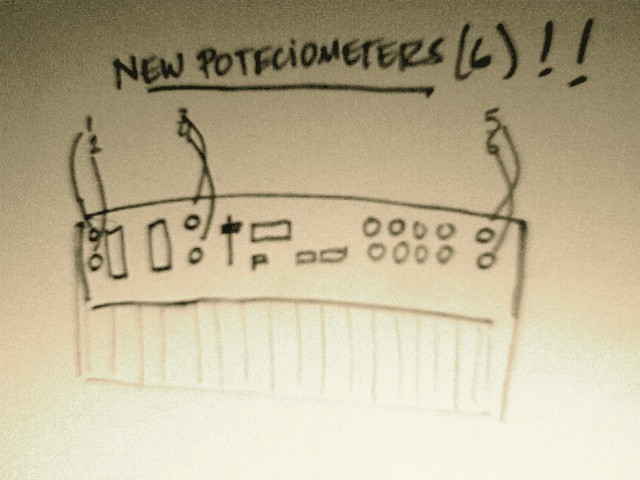
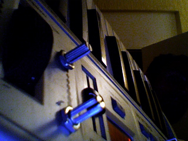
Yeap!!!
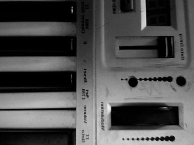
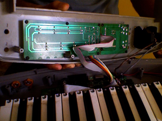
I decided to bend my Oxygen 8 Keyboard! and build in a passive line mixer in there!!… with the assistance of Darsha of course. Here are two new potenciometers just installed I still have to find space for 4 more, and also a good place for the inputs (RCA) but it should look something close to the drawing!
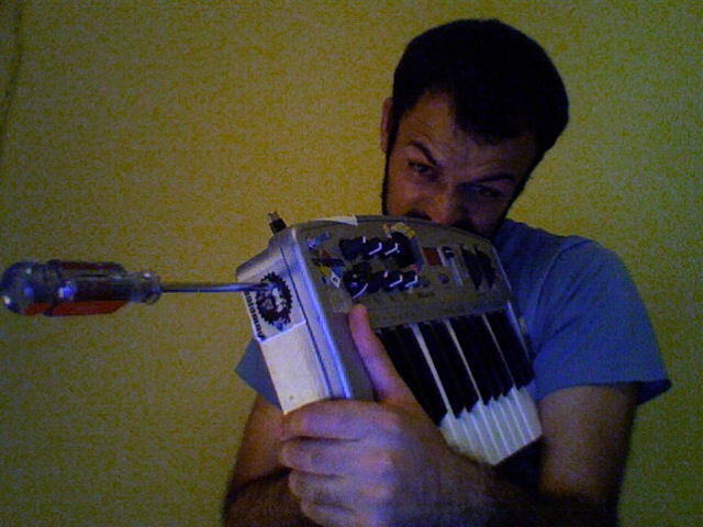
Jun 18th, 2008 by miau | No Comments »
Amplifying everiday

YA SE ROMPIO EL JUGUETE!
ok ok… no lo pude armar otra ves… en fin… hoy experimentamos con ruiditos de los juguetes y usamos nuevamente nuestro microfono piezzoelectrico que hicimos ayer mmm.. debe salir en la foto… en algun lugar… es como Donde esta wally …
porcierto llegando a mi casa me quede mirando la tele con un desarmador…. me gano el panico de pensar que no habia nada adentro.. ahhh!!!

Jun 18th, 2008 by chonk | No Comments »
que onda hijas, a continuacion les voy a mostrar brevemente como construyir un microfono de contacto para que utilicen como lo deseen.
Jun 18th, 2008 by chalux | No Comments »
awebo banda aqui andamos experimentando y aprendiendo sobre los mecanismos para conocer bien los procesos que nos conectan con el mundo tecnologico y electrico, la amplificacion de lo cotidiano nos acerca mas a la sonoridad que nos dan los objetos
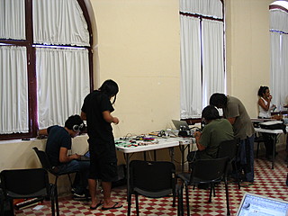
Jun 18th, 2008 by Alexandre Quessy | 1 Comment »
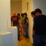
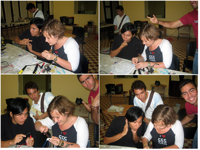
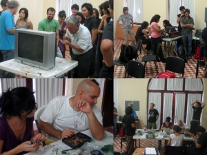
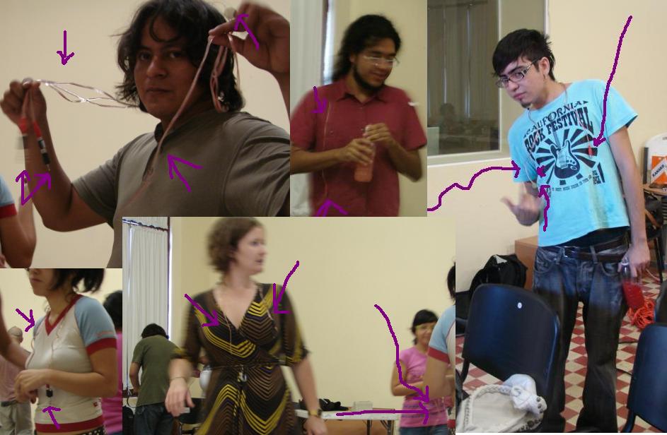
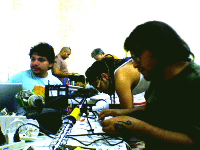
Aquí hay una serie de imágenes tomadas en el taller de ayer.
Jun 18th, 2008 by Tonalli | 2 Comments »
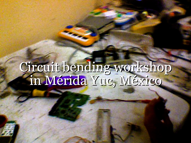
First Day Of Circuit Bending in Merida
On Monday June 15th the first circuit bending workshop in the peninsula of Yucatan was held at Esay´s Escuela de Artes visuales/ferrocarriles (Visual Arts School) by Two Canadian artists Darsha Hewit an Alexandre Quessy. It´s the first Circuit bending workshop ever in the Yucatan and hopefully not the last one, it will be 3 weeks long of fun and interaction with electronics, thirsty for knowledge students a squeaky roof and enough spanish practice to have our Canadian friends sing the Cucaracha.

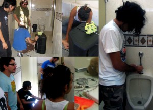
Piezo electric mics tour
On the second day we used a piezo component and converted it to a Mic after some basic soldering (soldering a RCA jack) the next asigment was using the piezo mic to amplify anything that we could think of. that is where the fun part started…. as you can imagine we tried everything till we ended up amplifying the schools bathroom…. nop! nobody was using them and more importantly nobody’s bladder was hurt! 😛
Here is RCA Jack
Jun 18th, 2008 by Alexandre Quessy | 2 Comments »
Hola.
My name is Alexandre Quessy. I am fascinated by electronics arts, interactive explorations, sounds, music, programming and much more. You can read me (in french) on my web site alexandre.quessy.net. I manage the DataFlow Wiki and am much involved into Montréal’s new media art scene.
Here is a little song through which you will know me a little better…
Acerca de
Contribuidores
- Aldo Leal
- Alexandre Quessy
- Amaury León Sosa
- Andrés Dájer
- Bárbara Galaz
- Byrt Wammack
- Carlo Canto
- Chonk
- Darío Arellano
- Darsha Hewitt
- Deborah Carnevali
- Denisse Acevedo
- Elías Puc
- Enrique Canto
- Gabriel Quintal
- Gabriel Ramírez
- Gema Rios
- Georgina Cetina
- Gonzalo Cardenas
- Isabel Martínez
- José Carlos Gaytán
- Joy Penroz
- Luis Leal Larroa
- Luis Miguel Catzin
- Manuel Estrella
- Omar Góngora
- Pedro Medina
- Pepe Molina
- Ragel Santana
- Ramón Rosado
- Ricardo Ramírez
- Tonali Magaña
- Vanessa Rodriguez
Participar
-
Categorías
-